


Network Cabling Help - Copyright © 2016 - All rights reserved. - Privacy and Cookie Policy


. . . but don't know where to start?
You could enroll for some formal training, there are a few recognised courses on structured cabling systems which offer some
hands-on experience, or you could take one of the many courses
offered by the manufacturers of cabling components. Obviously the
manufacturers try to sell their own products, but their courses are usually
cheaper and they can still provide some of the basic cabling skills.
There are also lots of books on the subject of cabling and a selection of these
can be found in the Network Cabling Help shop, or you could buy our kindle
eBook available from Amazon. The Network Cabling eBook contains far more
information than is on this website and will give you up to date information on the latest cabling
standards and classifications. Find out more here.
If you don't want to invest any money on training until you are seeing some financial results, then you
can gain valuable experience by actually doing some work for an existing cabling company.
Here are some basic questions you may be asking yourself if you have never installed a structured
cabling system before.
ISO/IEC 11801 - The International standard for structured cabling systems.
CENELEC EN 50173 - The European cabling standard.
The reason for having a 'Standard' is to define a method of connecting all types of vendors voice and
data equipment, over a cabling system that uses a common media, common connectors and a
common topology. This means that a building can be cabled for all its communications needs without
the planner or architect ever having to know what type of equipment will be used.
It is advisable to get a copy of one of the cabling standards documents, although once you have read
through it once and understood some of what it describes, it will probably be filed away and never
opened again. If you have ever tried to read a standards document you will know that it is hard work.
Trying to separate the useful information from all the technical jargon can be very time consuming and
even then you may not find the answer to your question. The bad news is, the Cabling Standards are
no different, they are full of cross references, formulas and tables all of which can be a very daunting
prospect and can make the installation engineer think twice about installing the stuff.
Now for the good news, the standards are mostly concerned with the performance criteria of the
components of a cabling system, and, as that is guaranteed by the manufacturers of the different
cabling components, you don't have to worry about it. Great eh!
of about 30m. Each double outlet will be used for one PC and one telephone. A detailed breakdown of
this list giving reasons for sizes and quantities is Here.
•
1 x 27U, 600 x 600 cabinet.
•
3 x 32 way RJ45 patch panels.
•
6 x boxes of Cat 5e cable.
•
30 x double Cat 5e outlets and backboxes
•
30 x PBX master telephone adapters
•
30 x 1.5m patch leads
•
30 x 2m patch leads
•
30 x 3m fly leads.
•
Trunking, cable ties and a method of labelling the system.
inclusive of patch and drop leads. Cable testers however, when set to perform a 'Basic Link' test, take
this into account and you will find that the maximum length is set to either 90m or 94m depending on
the standard you are testing to. Also, because the length is measured with a Cable Analyser it is not
the physical length of the run but the copper length that is measured. The copper length is longer due
to the twists in the cable pairs, so if a run looks like it might be over 85m it would be wise to check it
before it is tied up and terminated.
Each outlet cable should be run directly back to the patch cabinet, that is one cable per outlet. A
transition point or connection box is allowed if necessary, but in practice this can be more trouble than
its worth.
Care should be taken when pulling cables in to ensure that they are not kinked or nicked.
Cable routes should be planned to avoid fluorescent light fittings and power cables (exceptions can be
made in the case of optical fibre). They should not be run in the same conduit as power, or the same
channel of a trunking system, and where they are run parallel to power they must be at least 60mm
apart (BS7671-92) . Crossing power cables is allowed but it must be at right angles, and some form of
bridge should be used.
A means of supporting the cables should be installed such as cable tray, catenary wire or cable tie
fixings, tying cables to ceiling hangers is not permitted. Cables should be tied at a minimum of 500mm
intervals on horizontal runs and more frequently on vertical runs, with no more than 48 cables in a
loom. Cable ties should only be finger tight to avoid crushing the cables as this could affect the cables
performance characteristics. Do not use cable tie guns or staple guns.
Cable trays should be used under false floors, if not, a suitable method of keeping the cable off the
floor slab should be employed. This is because the lime in the concrete apparently reacts with the
cables sheathing, and over time could damage the cable. I personally think the cable will have outlived
its usefulness long before this could have any affect on the cables performance.
Care should be taken when pulling cables into trunking to avoid damage due to snagging. Trunking
partitions should be used to separate the data cables from power, and bridges should be used where
data cables have to cross the mains.
When terminating patch panels, cable looms should not exceed 48 cables. Each cable loom should
then be tied in a tidy manner to a cable tray fitted the full length of the cabinet.
All terminating should be carried out according to the manufacturers instructions and guidelines, and
the standards for generic cabling systems. The cable sheath should be stripped back no more than
13mm from the point of termination and the twist rates should be maintained.
Cable ties MUST be fitted to the individual RJ45 modules in the patch panels and outlets to support
each cable.
When terminating outlets, care must be taken to avoid damaging the copper cores when stripping back
the outer sheathing.
Excessive amounts of cable should not be left in the outlet backbox. Care should be taken when
attaching the outlet faceplate not to kink, trap or strain the cable.
Cable tray should be fitted in cabinets housing structured cabling to keep cable looms secure and tidy,
and to provide room for any additional cabling.
All cabinets must be earthed. Where shielded cable is used the earth should be clean and
where two cabinets are linked with a copper backbone (shielded or unshielded) a
minimum of 10mm² earth wire should also be installed to cross bond the cabinets.
be fully charged before testing begins. Descriptions of the various test parameters can be found on the
Cable Testing page.
On all installations, and particularly on large jobs, two way radios, mobile phones or internal telephone
lines should be used to ensure correct numbering of outlets and patch panels during testing.
cable. In the first diagram a coaxial cable is transmitting a 4V signal, this is unbalanced as all of the 4V
signal is carried by the centre core of the coax with respect to the grounded screen. If 1V of noise is
introduced, it adds to the signal being transmitted making 5V, this could interfere with our data.
With a balanced line transmission our 4V signal is split into +2V and -2V on one twisted pair, so we still
have 4V between the two. Now when we introduce the 1V of noise, the +2V becomes +3V, and the -2V
becomes -1V, but the potential difference between the two is still 4V. The devices we put on the ends of
the cable to make the line balanced are called baluns, this name is derived from the function of the
devices of converting between balanced and unbalanced transmission modes.
These days, more and more equipment is being designed to operate on balanced lines without the
need for baluns, but there are a few older systems out there that still use these converters.
Barratt should help to clear things up.
Bandwidth is the difference between the highest and lowest frequencies which will propagate through
an equipment or system. In many cases, the lower limit is DC, zero hertz, and so the bandwidth is the
same as the upper frequency limit. The public telephone system constrains all signals to the range 300
Hz - 3 kHz. Its bandwidth is therefore 2.7kHz.
In the most obvious method of modulation (representing data electrically), two different voltages are
used to represent a '1' and a '0'. The receiver expects a data bit at a certain time, and samples the
input voltage to determine the value of the bit. This is called "amplitude shift keying" (ASK). The
maximum frequency of the signal will depend upon the slew rate (the time taken to change from 0 to 1,
or vice versa). The maximum slew rate is the upper frequency limit, and the slew rate, in turn, limits the
maximum data rate.
Plainly, the bandwidth of such a system directly limits the data rate, but in theory it need not. Consider
a protocol which uses "frequency shift keying" instead. Here, two different
frequencies (both of them within the legal bandwidth) are used to represent 1
and 0. The maximum data rate is now the maximum speed at which you can
shift between the two frequencies. This is still limited by the bandwidth, but not
so directly - the resulting maximum data rate is higher. And what happens if you
use more than two frequencies? You can then transmit more than one bit of
information per signal transition, upping the data rate again without increasing
the maximum frequency of the signal.
It is techniques such as these which have allowed the development of 56k
modems. Using a combination of multiple-level amplitude, frequency and phase
modulation, they manage to extract up to 56,000 bits per second of performance
from the aforementioned 2.7 kHz bandwidth. To achieve this using plain 2-level
ASK would require a bandwidth of hundreds of kilohertz.
"Baud rate", strictly, is a measure of "signal elements" per second, and is not a useful measure where
the above signalling techniques are being used.
Such systems are generally rated in "bits per
second" bps. It is worth noting that manufacturers
will claim the highest figure they can for this
parameter, so that the figure will include bits which
are part of the signalling protocol rather than the
user's data, and may even incorporate an
assumption about the compressibility of the data. It
is rarely (if ever) valid to divide bps by 8 to arrive at
bytes of data transmitted/expected per second.
Written by
Mark Barratt
recognised courses on structured cabling systems which offer some
hands-on experience, or you could take one of the many courses
offered by the manufacturers of cabling components. Obviously the
manufacturers try to sell their own products, but their courses are usually
cheaper and they can still provide some of the basic cabling skills.
There are also lots of books on the subject of cabling and a selection of these
can be found in the Network Cabling Help shop, or you could buy our kindle
eBook available from Amazon. The Network Cabling eBook contains far more
information than is on this website and will give you up to date information on the latest cabling
standards and classifications. Find out more here.
If you don't want to invest any money on training until you are seeing some financial results, then you
can gain valuable experience by actually doing some work for an existing cabling company.
Here are some basic questions you may be asking yourself if you have never installed a structured
cabling system before.
What are 'The standards' ?
There are three main cabling standards: EIA/TIA 568A - This is the American standard and was the first to be published (1991).
ISO/IEC 11801 - The International standard for structured cabling systems.
CENELEC EN 50173 - The European cabling standard.
The reason for having a 'Standard' is to define a method of connecting all types of vendors voice and
data equipment, over a cabling system that uses a common media, common connectors and a
common topology. This means that a building can be cabled for all its communications needs without
the planner or architect ever having to know what type of equipment will be used.
It is advisable to get a copy of one of the cabling standards documents, although once you have read
through it once and understood some of what it describes, it will probably be filed away and never
opened again. If you have ever tried to read a standards document you will know that it is hard work.
Trying to separate the useful information from all the technical jargon can be very time consuming and
even then you may not find the answer to your question. The bad news is, the Cabling Standards are
no different, they are full of cross references, formulas and tables all of which can be a very daunting
prospect and can make the installation engineer think twice about installing the stuff.
Now for the good news, the standards are mostly concerned with the performance criteria of the
components of a cabling system, and, as that is guaranteed by the manufacturers of the different
cabling components, you don't have to worry about it. Great eh!
What type of cable do I install?
Please go to the Questions and Opinions page for my personal views on the subject.What materials do I need?
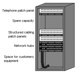
Lets work on a hypothetical installation. It is for 30 double outlets, in one building, with an average run
of about 30m. Each double outlet will be used for one PC and one telephone. A detailed breakdown of
this list giving reasons for sizes and quantities is Here.
•
1 x 27U, 600 x 600 cabinet.
•
3 x 32 way RJ45 patch panels.
•
6 x boxes of Cat 5e cable.
•
30 x double Cat 5e outlets and backboxes
•
30 x PBX master telephone adapters
•
30 x 1.5m patch leads
•
30 x 2m patch leads
•
30 x 3m fly leads.
•
Trunking, cable ties and a method of labelling the system.
How do I install it?
Here are the basic do's and don'ts. Although the maximum cable length for a Cat 5e/6/7 system is often reported to be 100m, this length is
inclusive of patch and drop leads. Cable testers however, when set to perform a 'Basic Link' test, take
this into account and you will find that the maximum length is set to either 90m or 94m depending on
the standard you are testing to. Also, because the length is measured with a Cable Analyser it is not
the physical length of the run but the copper length that is measured. The copper length is longer due
to the twists in the cable pairs, so if a run looks like it might be over 85m it would be wise to check it
before it is tied up and terminated.
Each outlet cable should be run directly back to the patch cabinet, that is one cable per outlet. A
transition point or connection box is allowed if necessary, but in practice this can be more trouble than
its worth.
Care should be taken when pulling cables in to ensure that they are not kinked or nicked.
Cable routes should be planned to avoid fluorescent light fittings and power cables (exceptions can be
made in the case of optical fibre). They should not be run in the same conduit as power, or the same
channel of a trunking system, and where they are run parallel to power they must be at least 60mm
apart (BS7671-92) . Crossing power cables is allowed but it must be at right angles, and some form of
bridge should be used.
A means of supporting the cables should be installed such as cable tray, catenary wire or cable tie
fixings, tying cables to ceiling hangers is not permitted. Cables should be tied at a minimum of 500mm
intervals on horizontal runs and more frequently on vertical runs, with no more than 48 cables in a
loom. Cable ties should only be finger tight to avoid crushing the cables as this could affect the cables
performance characteristics. Do not use cable tie guns or staple guns.
Cable trays should be used under false floors, if not, a suitable method of keeping the cable off the
floor slab should be employed. This is because the lime in the concrete apparently reacts with the
cables sheathing, and over time could damage the cable. I personally think the cable will have outlived
its usefulness long before this could have any affect on the cables performance.
Care should be taken when pulling cables into trunking to avoid damage due to snagging. Trunking
partitions should be used to separate the data cables from power, and bridges should be used where
data cables have to cross the mains.
When terminating patch panels, cable looms should not exceed 48 cables. Each cable loom should
then be tied in a tidy manner to a cable tray fitted the full length of the cabinet.
All terminating should be carried out according to the manufacturers instructions and guidelines, and
the standards for generic cabling systems. The cable sheath should be stripped back no more than
13mm from the point of termination and the twist rates should be maintained.
Cable ties MUST be fitted to the individual RJ45 modules in the patch panels and outlets to support
each cable.
When terminating outlets, care must be taken to avoid damaging the copper cores when stripping back
the outer sheathing.
Excessive amounts of cable should not be left in the outlet backbox. Care should be taken when
attaching the outlet faceplate not to kink, trap or strain the cable.
Cable tray should be fitted in cabinets housing structured cabling to keep cable looms secure and tidy,
and to provide room for any additional cabling.
All cabinets must be earthed. Where shielded cable is used the earth should be clean and
where two cabinets are linked with a copper backbone (shielded or unshielded) a
minimum of 10mm² earth wire should also be installed to cross bond the cabinets.
Testing and documentation
All testing whether copper or fibre should begin with calibration of test equipment, and batteries should
be fully charged before testing begins. Descriptions of the various test parameters can be found on the
Cable Testing page.
On all installations, and particularly on large jobs, two way radios, mobile phones or internal telephone
lines should be used to ensure correct numbering of outlets and patch panels during testing.
What do they mean by Balanced line? How does it work?
Balanced line operation is a transmission method which helps to eliminate the effects of noise on the
cable. In the first diagram a coaxial cable is transmitting a 4V signal, this is unbalanced as all of the 4V
signal is carried by the centre core of the coax with respect to the grounded screen. If 1V of noise is
introduced, it adds to the signal being transmitted making 5V, this could interfere with our data.
With a balanced line transmission our 4V signal is split into +2V and -2V on one twisted pair, so we still
have 4V between the two. Now when we introduce the 1V of noise, the +2V becomes +3V, and the -2V
becomes -1V, but the potential difference between the two is still 4V. The devices we put on the ends of
the cable to make the line balanced are called baluns, this name is derived from the function of the
devices of converting between balanced and unbalanced transmission modes.
These days, more and more equipment is being designed to operate on balanced lines without the
need for baluns, but there are a few older systems out there that still use these converters.
MHz? Mbps? Baud?
If you are confused about the different terms used in data communications this article written by Mark
Barratt should help to clear things up.
Bandwidth is the difference between the highest and lowest frequencies which will propagate through
an equipment or system. In many cases, the lower limit is DC, zero hertz, and so the bandwidth is the
same as the upper frequency limit. The public telephone system constrains all signals to the range 300
Hz - 3 kHz. Its bandwidth is therefore 2.7kHz.
In the most obvious method of modulation (representing data electrically), two different voltages are
used to represent a '1' and a '0'. The receiver expects a data bit at a certain time, and samples the
input voltage to determine the value of the bit. This is called "amplitude shift keying" (ASK). The
maximum frequency of the signal will depend upon the slew rate (the time taken to change from 0 to 1,
or vice versa). The maximum slew rate is the upper frequency limit, and the slew rate, in turn, limits the
maximum data rate.
Plainly, the bandwidth of such a system directly limits the data rate, but in theory it need not. Consider
a protocol which uses "frequency shift keying" instead. Here, two different
frequencies (both of them within the legal bandwidth) are used to represent 1
and 0. The maximum data rate is now the maximum speed at which you can
shift between the two frequencies. This is still limited by the bandwidth, but not
so directly - the resulting maximum data rate is higher. And what happens if you
use more than two frequencies? You can then transmit more than one bit of
information per signal transition, upping the data rate again without increasing
the maximum frequency of the signal.
It is techniques such as these which have allowed the development of 56k
modems. Using a combination of multiple-level amplitude, frequency and phase
modulation, they manage to extract up to 56,000 bits per second of performance
from the aforementioned 2.7 kHz bandwidth. To achieve this using plain 2-level
ASK would require a bandwidth of hundreds of kilohertz.
"Baud rate", strictly, is a measure of "signal elements" per second, and is not a useful measure where
the above signalling techniques are being used.
Such systems are generally rated in "bits per
second" bps. It is worth noting that manufacturers
will claim the highest figure they can for this
parameter, so that the figure will include bits which
are part of the signalling protocol rather than the
user's data, and may even incorporate an
assumption about the compressibility of the data. It
is rarely (if ever) valid to divide bps by 8 to arrive at
bytes of data transmitted/expected per second.
Written by
Mark Barratt


So you want to install some network cables . . .


