


Network Cabling Help - Copyright © 2016 - All rights reserved. - Privacy and Cookie Policy


The installation and termination of optical fibers used to be regarded as somewhat of a 'Black Art' but with standardization and easier terminating techniques this is no
longer true. A basic knowledge of the subject, together with a quick lesson and
some practice can get you started in fiber optics, but to really understand the
subject and gain full in-depth knowledge will require some formal training.
There are lots of Fibre Optic training companies offering recognised qualifications
and a quick search on the net should find one in your area.
There are also hundreds of books on fiber optics and a search on Network Cabling
Help book store will find over 2200 titles. Without reviewing them all it is difficult to
know what to recommend, but two of the best sellers in this category seem to follow
on quite nicely from this page without getting too involved with mathematics. The
two books are the Fiber Optic Installer's Field Manual by Bob Chomycz and Understanding Fiber Optics,
Fifth Edition by Jeff Hecht.
Right, lets get on with the lesson
of a stream of water pouring from a container, it was this simple
principle that led to the study and development of applications
for this phenomenon. John Logie Baird patented a method of
transmitting light in a glass rod for use in an early colour TV, but
the optical losses inherent in the materials at the time made it impractical to
use. In the 1950's more research and development into the transmission of visible images through optical
fibres led to some success in the medical world, as they began using them in remote illumination and
viewing instruments. In 1966 Charles Kao and George Hockham proposed the transmission of
information over glass fibre, and they also realised that to make it a practical proposition, much lower
losses in the cables were essential. This was the driving force behind the developments to improve the
optical losses in fibre manufacturing, and today optical losses are significantly lower than the original
target set out by Charles Kao and George Hockham.
distances than copper cables, in data networks this can be as much as 2km without the use of repeaters.
Their light weight and small size also make them ideal for applications where running copper cables
would be impractical, and by using multiplexors one fiber could replace hundreds of copper cables. This
is pretty impressive for a tiny glass filament, but the real benefits in the data industry are its immunity to
Electro Magnetic Interference (EMI), and the fact that glass is not an electrical conductor. Because fiber
is non-conductive, it can be used where electrical isolation is needed, for instance between buildings
where copper cables would require cross bonding to eliminate differences in earth potentials. Fibers also
pose no threat in dangerous environments such as chemical plants where a spark could trigger an
explosion. Last but not least is the security aspect, it is very, very difficult to tap into a fibre cable to read
the data signals.
one of the most common types, 62.5/125 micron loose tube. The numbers represent the diameters of the
fibre core and cladding, these are measured in microns which are millionths of a metre. Loose tube fibre
cable can be indoor or outdoor, or both, the outdoor cables usually have the tube filled with gel to act as
a moisture barrier which stops the ingress of water. The number of cores in one cable can be anywhere
from 4 to 144
Over the years a variety of core sizes have been produced but these days there are only three main
sizes that are used in data communications, these are 50/125, 62.5/125 and 8.3/125. The 50/125 and
62.5/125 micron multi-mode cables are the most widely used in data networks, although recently the 62.5
has become the more popular choice. This is rather unfortunate, because the 50/125 has been found to
be the better option for Gigabit Ethernet applications.
The 8.3/125 micron is a single mode cable which until now hasn't been widely used in data networking,
this was due to the high cost of single mode hardware. Things are beginning to change because the
length limits for Gigabit Ethernet over 62.5/125 fibre has been reduced to around 220m, and now, using
8.3/125 may be the only choice for some campus size networks. Hopefully, this shift to single mode may
start to bring the costs down.
opposite is true. To explain this we first need to understand how the light propagates within the fibre core.
by using two types of glass which have different refractive indexes. The inner core has a high refractive
index and the outer cladding has a low index. This is the same principle as the reflection you see when
you look into a pond. The water in the pond has a higher refractive index than the air, and if you look at it
from a shallow angle you will see a reflection of the surrounding area, however, if you look straight down
at the water you can see the bottom of the pond. At some specific angle between these two view points
the light stops reflecting off the surface of the water and passes through the air/water interface allowing
you to see the bottom of the pond. In multi-mode fibres, as the name suggests, there are multiple modes
of propagation for the rays of light. These range from low order modes which take the most direct route
straight down the middle, to high order modes which take the longest route as they bounce from one side
to the other all the way down the fibre.
This has the effect of scattering the signal because the rays from one pulse of light, arrive at the far end
at different times, this is known as Intermodal Dispersion (sometimes referred to as Differential Mode
Delay, DMD). To ease the problem, graded index fibres were developed. Unlike the examples above
which have a definite barrier between core and cladding, these have a high refractive index at the centre
which gradually reduces to a low refractive index at
the circumference. This slows down the lower order
modes allowing the rays to arrive at the far end
closer together, thereby reducing intermodal
dispersion and improving the shape of the signal.
Dispersion?, easy, only allow one mode of
propagation. So a smaller core size means higher
bandwidth and greater distances.
of a 'Black Art' but with standardization and easier terminating techniques this is no
longer true. A basic knowledge of the subject, together with a quick lesson and
some practice can get you started in fiber optics, but to really understand the
subject and gain full in-depth knowledge will require some formal training.
There are lots of Fibre Optic training companies offering recognised qualifications
and a quick search on the net should find one in your area.
There are also hundreds of books on fiber optics and a search on Network Cabling
Help book store will find over 2200 titles. Without reviewing them all it is difficult to
know what to recommend, but two of the best sellers in this category seem to follow
on quite nicely from this page without getting too involved with mathematics. The
two books are the Fiber Optic Installer's Field Manual by Bob Chomycz and Understanding Fiber Optics,
Fifth Edition by Jeff Hecht.
Right, lets get on with the lesson
First a bit history
In 1870, John Tyndall demonstrated that light follows the curve
of a stream of water pouring from a container, it was this simple
principle that led to the study and development of applications
for this phenomenon. John Logie Baird patented a method of
transmitting light in a glass rod for use in an early colour TV, but
the optical losses inherent in the materials at the time made it impractical to
use. In the 1950's more research and development into the transmission of visible images through optical
fibres led to some success in the medical world, as they began using them in remote illumination and
viewing instruments. In 1966 Charles Kao and George Hockham proposed the transmission of
information over glass fibre, and they also realised that to make it a practical proposition, much lower
losses in the cables were essential. This was the driving force behind the developments to improve the
optical losses in fibre manufacturing, and today optical losses are significantly lower than the original
target set out by Charles Kao and George Hockham.
The advantages of using fiber optics
Because of the Low loss, high bandwidth properties of fiber cable they can be used over greater
distances than copper cables, in data networks this can be as much as 2km without the use of repeaters.
Their light weight and small size also make them ideal for applications where running copper cables
would be impractical, and by using multiplexors one fiber could replace hundreds of copper cables. This
is pretty impressive for a tiny glass filament, but the real benefits in the data industry are its immunity to
Electro Magnetic Interference (EMI), and the fact that glass is not an electrical conductor. Because fiber
is non-conductive, it can be used where electrical isolation is needed, for instance between buildings
where copper cables would require cross bonding to eliminate differences in earth potentials. Fibers also
pose no threat in dangerous environments such as chemical plants where a spark could trigger an
explosion. Last but not least is the security aspect, it is very, very difficult to tap into a fibre cable to read
the data signals.
Fibre construction
There are many different types of fiber cable, but for the purposes of this explanation we will deal with
one of the most common types, 62.5/125 micron loose tube. The numbers represent the diameters of the
fibre core and cladding, these are measured in microns which are millionths of a metre. Loose tube fibre
cable can be indoor or outdoor, or both, the outdoor cables usually have the tube filled with gel to act as
a moisture barrier which stops the ingress of water. The number of cores in one cable can be anywhere
from 4 to 144
Over the years a variety of core sizes have been produced but these days there are only three main
sizes that are used in data communications, these are 50/125, 62.5/125 and 8.3/125. The 50/125 and
62.5/125 micron multi-mode cables are the most widely used in data networks, although recently the 62.5
has become the more popular choice. This is rather unfortunate, because the 50/125 has been found to
be the better option for Gigabit Ethernet applications.
The 8.3/125 micron is a single mode cable which until now hasn't been widely used in data networking,
this was due to the high cost of single mode hardware. Things are beginning to change because the
length limits for Gigabit Ethernet over 62.5/125 fibre has been reduced to around 220m, and now, using
8.3/125 may be the only choice for some campus size networks. Hopefully, this shift to single mode may
start to bring the costs down.
What's the difference between single-mode and multi-mode?
With copper cables larger size means less resistance and therefore more current, but with fibre the
opposite is true. To explain this we first need to understand how the light propagates within the fibre core.
Light propagation
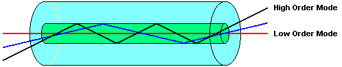
Light travels along a fiber cable by a process called 'Total Internal Reflection' (TIR), this is made possible
by using two types of glass which have different refractive indexes. The inner core has a high refractive
index and the outer cladding has a low index. This is the same principle as the reflection you see when
you look into a pond. The water in the pond has a higher refractive index than the air, and if you look at it
from a shallow angle you will see a reflection of the surrounding area, however, if you look straight down
at the water you can see the bottom of the pond. At some specific angle between these two view points
the light stops reflecting off the surface of the water and passes through the air/water interface allowing
you to see the bottom of the pond. In multi-mode fibres, as the name suggests, there are multiple modes
of propagation for the rays of light. These range from low order modes which take the most direct route
straight down the middle, to high order modes which take the longest route as they bounce from one side
to the other all the way down the fibre.
This has the effect of scattering the signal because the rays from one pulse of light, arrive at the far end
at different times, this is known as Intermodal Dispersion (sometimes referred to as Differential Mode
Delay, DMD). To ease the problem, graded index fibres were developed. Unlike the examples above
which have a definite barrier between core and cladding, these have a high refractive index at the centre
which gradually reduces to a low refractive index at
the circumference. This slows down the lower order
modes allowing the rays to arrive at the far end
closer together, thereby reducing intermodal
dispersion and improving the shape of the signal.
So what about the single-mode fibre?
Well, what's the best way to get rid of Intermodal
Dispersion?, easy, only allow one mode of
propagation. So a smaller core size means higher
bandwidth and greater distances.
Fiber Optics