
ACR
The first thing to understand about testing
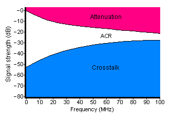
data cables is the ACR,
this stands for Attenuation
to Crosstalk Ratio. The
pink area in the graph is
the attenuation, this can be
caused by several things
as will be explained below,
and the blue area is the
crosstalk. Attenuation is the reduction in signal strength over the length of the
cable and frequency range, the crosstalk is the external noise that is introduced into the cable. So, if
the two areas meet, the data signal will be lost because the crosstalk noise will be at the same level as
the attenuated signal.
ACR is the most important result when testing a link because it represents the overall performance of
the cable.
understand about testing
data cables is the ACR,
this stands for Attenuation
to Crosstalk Ratio. The
pink area in the graph is
the attenuation, this can be
caused by several things
as will be explained below,
and the blue area is the
crosstalk. Attenuation is the reduction in signal strength over the length of the
cable and frequency range, the crosstalk is the external noise that is introduced into the cable. So, if
the two areas meet, the data signal will be lost because the crosstalk noise will be at the same level as
the attenuated signal.
ACR is the most important result when testing a link because it represents the overall performance of
the cable.
So what causes the signal to attenuate?, and where does the crosstalk come from?
Below are of some of the terms used in high performance cable testing, and a description of what they
mean.
Length
The length of a cable is one of the more obvious causes of attenuation because the longer it is, the
more resistance it has, and therefore less of the signal will get through. To measure the length, a cable
tester uses Time Domain Reflectometry (TDR). A pulse is sent down the cable and when it reaches the
far end it reflects back, by measuring the time it takes to travel down the cable and back again, the
tester can determine how long the cable is. To do this, the tester also needs to know how fast the
pulsed signal is travelling, this is called the Nominal Velocity of Propagation (NVP) and is expressed as
a percentage of the speed of light. The NVP is usually somewhere between 60% and 90% of the speed
of light, with most Cat 5E/6/6a/7/7a cables being around 70%. Due to the twists in the cable, the
measured length will be greater than the physical length, so if a run looks like it might be over 80m it
would be wise to check it before it is tied up and terminated.
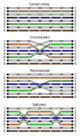
Wire Map
This test is to ensure that the two ends have been
terminated pin for pin, i.e. that pin 1 at the patch panel goes
to pin 1 at the outlet, pin 2 goes to pin 2 etc. etc. The wire
map also checks for continuity, shorts, crossed pairs,
reversed pairs and split pairs. A Split pair is probably the
only thing that requires an explanation here, as they are
undetectable with a simple continuity tester, this is because
pin for pin they seem to be correct. As explained on the
Cabling Basics page, balanced line operation requires that
the signal is transmitted over a pair of wires that are twisted
together, with a 'split pair' the signal would be split between
two different pairs.
Return Loss
When a cable is manufactured there are slight
imperfections in the copper. These imperfections all
contribute to the Structural Return Loss (SRL)
measurement because each one causes an impedance
mismatch which adds to the cables attenuation.
DC loop resistance
This is simply the resistance between the two conductors of a twisted pair which is looped back at the
far end. The primary purpose of this test is to make sure that there are no high resistance connections
in the link.
Attenuation
This is the decrease in signal strength (expressed as negative dB) from one end of a cable to the other. The main causes of attenuation are impedance, temperature, skin effect and dielectric loss. Impedance
is the combination of resistance, inductance and capacitance in a cable, it is measured in Ohms and
opposes the flow of current. Skin effect is phenomena which happens at high frequencies where the
signal tries to escape from the confines of the copper and into the air. The signal travels along the outer
'skin' of the copper which effectively reduces the cross sectional area of the cable and therefore
increases its resistance.
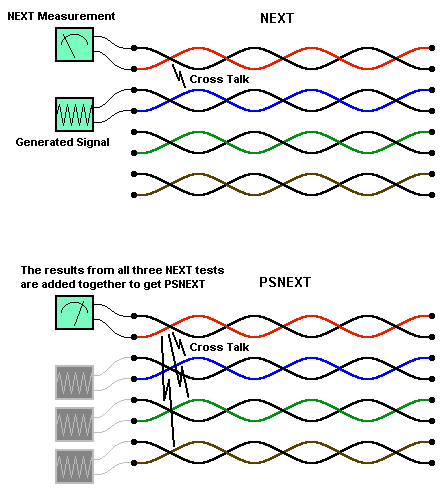
NEXT
This stands for Near End cross
Talk, and it occurs because
alternating current flow
produces an electromagnetic
field around the cable, this field
then induces a current flow in
adjacent cables. The strength of
this field increases with the
frequency of the signal, and
because the speed of data
transmissions is ever
increasing, NEXT is a big
problem.
The name 'Cross Talk' comes
from the telecommunications
industry, you may have heard a
faint conversation in the
background while on the phone
yourself, this is caused by the
electromagnetic effect between
adjacent telephone wires. In the
transmission of data, cross talk
is at its highest level in the RJ45 connection as it enters the cable, or at the 'Near End'. The term 'Near
End' is slightly confusing because data can travel in both directions, and the NEXT test is carried out in
both directions automatically by the tester, so the NEXT result is relative to the end of the cable that it
was carried out on.
The twists in a cable help to cancel out the effects of NEXT and the more twists there are, the better
the cancellation, however, the twists also increase attenuation, so there is a trade off between NEXT
cancellation and attenuation. The twist rates in data cables are optimised for the best overall
performance, the twist rates are also varied for each pair within the cable to help combat crosstalk.
PSNEXT
This stands for Power Sum Near End Cross Talk and is actually just a calculation. When a tester
carries out the NEXT test it measures the cross talk on each pair as affected by each of the other three
pairs individually, PSNEXT is simply the addition of the three NEXT results for each pair. So this is the
combined effect that a pair would be subject to when used in a network that supports a four pair
transmissions method, e.g.. Gigabit Ethernet.
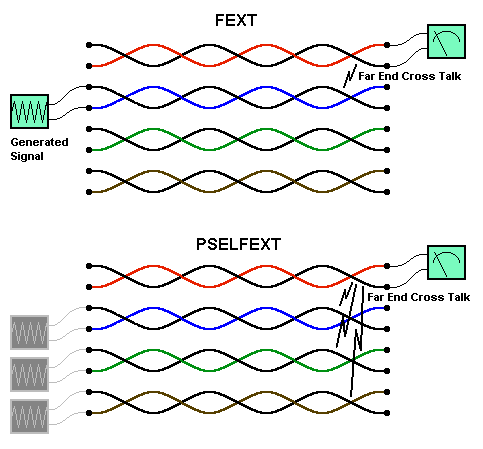
FEXT, ELFEXT and
PSELFEXT
Basically, Far End Cross
Talk (FEXT) is like NEXT
but it is measured at the
far end (well that seems
logical!). However, on its
own FEXT doesn't mean
much because the length
of the cable determines
how much the signal is
attenuated before it can
affect the pairs at the far
end. To compensate for
this, and to provide a more
meaningful result, the
attenuation is subtracted
from the FEXT test and the
result is then called Equal
Level Far End Cross Talk
(ELFEXT).
And of course, no test
parameter these days would be complete without adding the results together for each pair and calling it
a Power Sum measurement, so now we have Power Sum Equal Level Far End Cross Talk or
PSELFEXT for short. There is now a new term for ELFEXT which is "Attenuation to Crosstalk Ratio,
Far-end" (or ACRF).
Delay
This is the propagation delay or the time it takes for the signal to travel from one end of the cable to the other, it is not very important on it own because its value is directly proportional to the length of the
cable. What is important is the relationship between the delays on each of the four pairs. This brings us
nicely on to .........................
Delay Skew
Now this is important, Delay Skew is the difference
between the fastest and slowest pairs. Some
networks use a four pair transmission method, this
means that the signal is split into four, sent down the
four pairs in the cable and re-combined at the far
end. It is essential that the signals reach the far end
at near enough the same time, otherwise the signal
will not be re-combined correctly.


Network Cabling Help - Copyright © 2016 - All rights reserved. - Privacy and Cookie Policy

Cable Testing


